
The fluxgate current sensor measures current by utilizing the nonlinear relationship between the magnetic induction intensity and the magnetic field intensity of a high-permeability magnetic core under the saturation excitation of an alternating magnetic field.
When the fluxgate current sensor is working, a square wave is loaded in the excitation coil to magnetize the magnetic core back and forth to saturation. When the measured current is zero, the excitation voltage signal in the magnetic core and the excitation current in the coil are completely symmetric, and the output is zero. When the measured current is not zero, the excitation current and the measured current act on the magnetic core simultaneously, and the current waveform in the coil is no longer symmetric. By processing it, the measurement of the measured current is completed.
KTD1100 mainly includes an excitation power supply circuit and a signal conditioning circuit. The excitation power supply is a voltage excitation source with a driving capability of 100mA. The signal conditioning circuit includes a voltage reference source, a comparator, a signal logic processing unit, and an independent three-channel operational amplifier, which is used for control, signal amplification, filtering, and output.
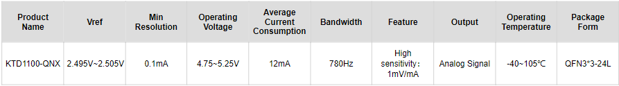
| Product Name | Vref | Min Resolution | Operating Voltage | Average Current Consumption | Bandwidth | Feature | Output | Operating Temperature | Package Form |
|---|---|---|---|---|---|---|---|---|---|
| KTD1100-QNX | 2.495V~2.505V | 0.1mA | 4.75~5.25V | 12mA | 780Hz | High sensitivity:1mV/mA | Analog Signal | -40~105℃ | QFN3*3-24L |